


 live:.cid.d7553a84e2f43ba0


Focus on customer needs and to be a reliable battery testing service provider


Artical from: https://eepower.com/technical-articles/reading-ohmmeter-resistance-measurements/
Ohmmeter resistance measurements are taken to determine the resistance of de-energized (having all power OFF) components or circuits. Analog ohmmeters or digital ohmmeters are used to take resistance measurements.
Analog Ohmmeters
Analog ohmmeters have a function switch that must be set to ohms and a selector switch that must be set to a range position (Ω, R × 1, R × 100, R × 1K, or R × 10,000). Because resistance measurements are taken using the internal batteries of an ohmmeter, the pointer of the meter must be zeroed for the condition of the batteries before taking any resistance measurements. The pointer of an analog ohmmeter is zeroed by connecting the two test leads together and adjusting the zero adjuster control knob until the pointer is on 0 Ω. Zeroing the pointer must be performed each time the ohmmeter function switch or selector switch positions are changed to a different range because battery condition affects resistance measurements (see Figure 1).
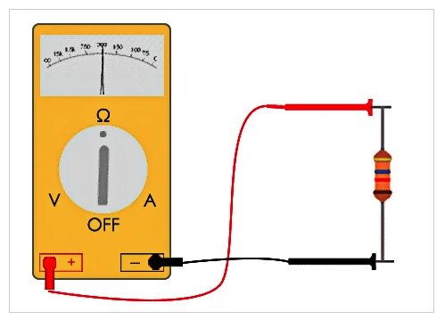
Figure 1. Analog and digital ohmmeters must be set to zero before any resistance measurements are performed.
Digital Ohmmeters
Digital ohmmeters have a function switch that must be set to the resistance measurement (Ω) mode. As with analog ohmmeters, digital ohmmeters also use internal batteries to take resistance measurements. Digital ohmmeters are zeroed (meter reads resistance of test leads) by setting the function switch of the meter to the resistance measurement (Ω) position and touching the two test leads of the meter together. Some digital ohmmeters read the resistance of the test leads, while other ohmmeters automatically set to zero. When the resistance of the test leads is displayed, the displayed resistance of the test leads is eliminated by pressing the relative mode (REL) button on the digital ohmmeter zeroing the meter.
Ohmmeter Applications
Ohmmeter measurements are not only used to determine the resistance of a circuit or component but are also used to determine the type or wiring of a component being tested. For example, an ohmmeter being used for a resistance test can be used to determine if a 9-lead, 3ϕ motor is wye or delta connected and if the windings of the motor are in good condition.
Ohmmeters are used to test for open and short motor windings and/or to test the resistance of the windings. An open winding of a motor is displayed as an overload (OL). A shorted motor winding is displayed as 0 Ω or as a lower than normal winding resistance (see Figure 2).
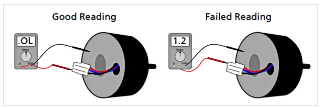
Figure 2. Ohmmeters are used to determine if the windings are open or shorted.
Ohmmeters measure the resistance on de-energized circuits or components. Low voltages from circuits applied to ohmmeters set to measure resistance cause inaccurate readings and possible meter damage. High voltages from circuits applied to ohmmeters set to measure resistance cause ohmmeter damage, even when the DMM has internal protection. Always verify that circuits or components do not have voltage before taking any resistance measurements.
Ohmmeter Measurement Procedures
Before taking any resistance measurements using an ohmmeter, ensure the meter is designed to take measurements on the circuit being tested. See Figure 3. For all measuring precautions, restrictions, and procedures, consult the test instrument's operating manual. Always wear required personal protective equipment and follow all safety rules when taking the measurement. Resistance is measured with test instruments that include a resistance measurement mode by applying the following procedures:
1. Verify that all power is OFF to the circuit and remove the component being tested from the circuit.
2. Set the ohmmeter function switch to the resistance mode as required. Test instruments display OL and the ohm (Ω) symbol when set to the resistance mode.
3. Plug the black test lead into the common jack when required.
4. Plug the red test lead into the resistance jack when required.
5. Ensure that the batteries of the test instrument are in good condition. Most digital meters display the battery symbol when the batteries are low.
6. Zero the ohmmeter. When the test leads of the ohmmeter are connected together, the display of the meter should read 0 Ω. However, the resistance of the test leads (typically 0.2 Ω to 0.5 Ω) may be displayed and can affect a very low resistance measurement when the ohmmeter does not have a relative mode button to set the meter to zero.
7. Connect the test leads across the circuit or component being tested. Ensure that the contact between the test leads and the circuit or component is correct. Dirt, solder flux, oil, and other foreign substances greatly affect resistance readings. Also, any contact with the metal ends of the test leads by the fingers of the electrician during the resistance test affects the resistance measurement.
8. Read the resistance measurement displayed on the ohmmeter.
9. After completing all resistance measurements, remove the ohmmeter from the circuit or component and turn the meter OFF to prevent battery drain.
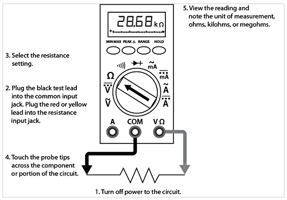
Figure 3. Electricians must always verify that circuits or components do not have voltage before taking any resistance measurements. Image courtesy of LibreTexts
Technical Tip
Only batteries approved by the manufacturer of a test instrument may be used in a test instrument. After removing the old batteries, the contacts of the new batteries and the battery holders of the test instrument must be cleaned. Ensure the correct polarity when inserting new batteries into holders.
Follow the procedure for battery replacement:
• Always replace all of the batteries at one time.
• Ensure that the polarity of the new batteries matches the test instrument.
• Dispose of used batteries properly, in an environmentally friendly manner.


 Global - English
